The Problem With Unground Forage
Long-stemmed hay and crop residues present a fundamental problem in modern livestock feeding: the animal cannot reliably consume them in a way that delivers consistent nutrition. Cattle sorting through a pile of unground hay will preferentially eat the leafy, seed-head fractions — the most nutritious parts — and leave behind the stalk fractions. The result is that the first animals in the pen get a high-energy, high-protein diet while later arrivals eat low-value stalk. On a feedlot or dairy operation where consistent animal performance is the goal, this variation is commercially damaging. A hammer-mill forage grinder eliminates sorting by reducing all feed fractions to the same particle size, forcing animals to consume the full nutritional profile of the forage regardless of their preference. Understanding how the grinder achieves this — exactly what happens inside the machine between raw bale and ground output — helps operators set it up correctly, maintain it effectively, and recognise when something is going wrong.
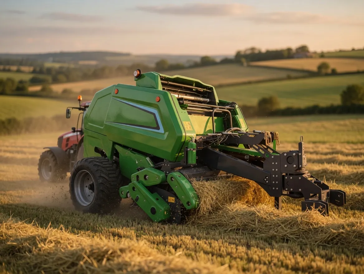
Forage baled and stored correctly feeds the hammer mill consistently — the quality entering the grinder determines the quality exiting it.
Stage One: Feed Infeed and Initial Fracture
Raw material enters the 9F-70 through the top-mounted feed inlet. Operators feed hay manually — flakes broken from a round or square bale — or use an optional conveyor that draws bale material in continuously at a controlled rate. The inlet is sized to accept blocks of material up to approximately 300 mm × 300 mm in cross-section. As material falls or is fed into the grinding chamber, it immediately encounters the rotor assembly spinning at 2,800–3,200 RPM.
The rotor is a heavy steel shaft carrying multiple rows of hammer pivot pins arranged around its circumference. Each pin holds one or two hammers — flat, rectangular pieces of hardened steel — that swing freely on the pin. This free-swinging design is important: when a hammer strikes a stone or metal contaminant, it swings back on its pivot rather than transmitting the full impact force into the rotor shaft. This protects the rotor from damage and reduces vibration during normal operation. The first contact between the material and the hammer tips is a high-velocity impact — tip speed runs 65–80 m/s — that fractures long stems into shorter segments immediately upon entry into the chamber.
Stage Two: Repeated Impact and Size Reduction
After initial fracture, partially reduced material circulates inside the grinding chamber, continuously struck by the rotating hammers. The grinding chamber wall — the area above the screen — is lined with breaker bars or serrated wear plates. These fixed protrusions catch material thrown outward by centrifugal force, slow it momentarily, and present it back into the hammer zone for another impact cycle. This interplay between the spinning hammers and the fixed breaker bars is where most of the size reduction work occurs.
The energy transferred per hammer strike depends on both hammer mass and tip speed. Heavier hammers carry more kinetic energy and fracture tough, dense materials like corn stover and dry straw more effectively. Lighter hammers are gentler and more appropriate for brittle, dry hay that shatters easily. The 9F-70 uses a medium-weight hammer profile that handles both hay and straw without requiring hammer changes — a practical choice for mixed-feed operations that grind multiple raw materials.
Material stays in the grinding chamber until it is small enough to pass through the screen. The combination of rotor speed, hammer mass, chamber geometry, and screen hole size means that the machine is self-regulating in one important sense: it does not release material until it meets the target particle size specification. Operators cannot over-grind by slowing down the feed rate; they can only change the output particle size by changing the screen.
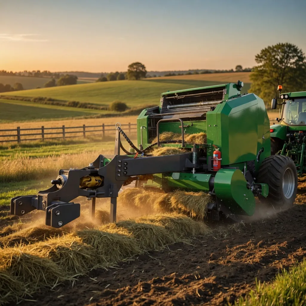
The quality of the forage bale — moisture, density, and species composition — determines how the hammer mill performs through every stage of the grinding process.
Stage Three: Screen Sizing and Discharge
The perforated screen wraps around the lower half of the rotor, covering approximately 180 degrees of the rotor circumference. As particles reach a size small enough to pass through the holes, centrifugal force pushes them outward through the screen and into the discharge plenum below. The screen is the primary determinant of output particle size: a 4 mm screen produces fine grind suitable for pellet infeed; a 6 mm screen produces medium grind for TMR and dairy rations; an 8–10 mm screen produces a coarse chop appropriate for dry cow rations, goat and sheep supplementation, or roughage bulking in high-grain feedlot diets.
Screen replacement on the 9F-70 requires removing four bolts, sliding the old screen out, inserting the new screen, and re-bolting — the full process takes 10–15 minutes with two people. This makes mid-day screen changes practical if the feed specification changes between morning and afternoon grinding runs. The 9F-70 is supplied with two screens as standard; additional screens are available from EverPower’s Condell Park warehouse for operations that need multiple particle sizes regularly.
Discharged material falls into the bottom collection zone and is moved by gravity or a centrifugal fan to the output system. The 9F-70 can discharge directly into a collection bag, a silo auger, a TMR mixer, or an elevated discharge chute — the configuration depends on the downstream process in the operation.
What Happens Inside the Machine: A Summary Diagram
How Hammer Condition Affects Output Quality
New hammers have sharp, well-defined edges. These edges bite into material fibres and fracture them cleanly, producing particles with clean cross-sections and consistent length. As hammers wear, the edges round off and the striking face becomes a blunt, rounded profile. Worn hammers tear rather than fracture — the result is a higher proportion of fine dust, longer recirculation time in the chamber, higher power draw per tonne of output, and a measurable increase in the percentage of oversized particles that somehow pass the screen edge without being fully reduced.
The practical signs of worn hammers are: throughput dropping below the machine’s rated capacity despite consistent feed quality and moisture; power draw (current draw on the electric motor) increasing for the same feed rate; output particle size becoming more variable, with more fines and occasional coarse outliers; and an increase in machine vibration as hammer mass becomes uneven across the rotor. The 9F-70 uses symmetric, reversible hammers — when one face wears, the hammer can be flipped 180 degrees to present the unworn face, effectively doubling hammer life before replacement is needed.
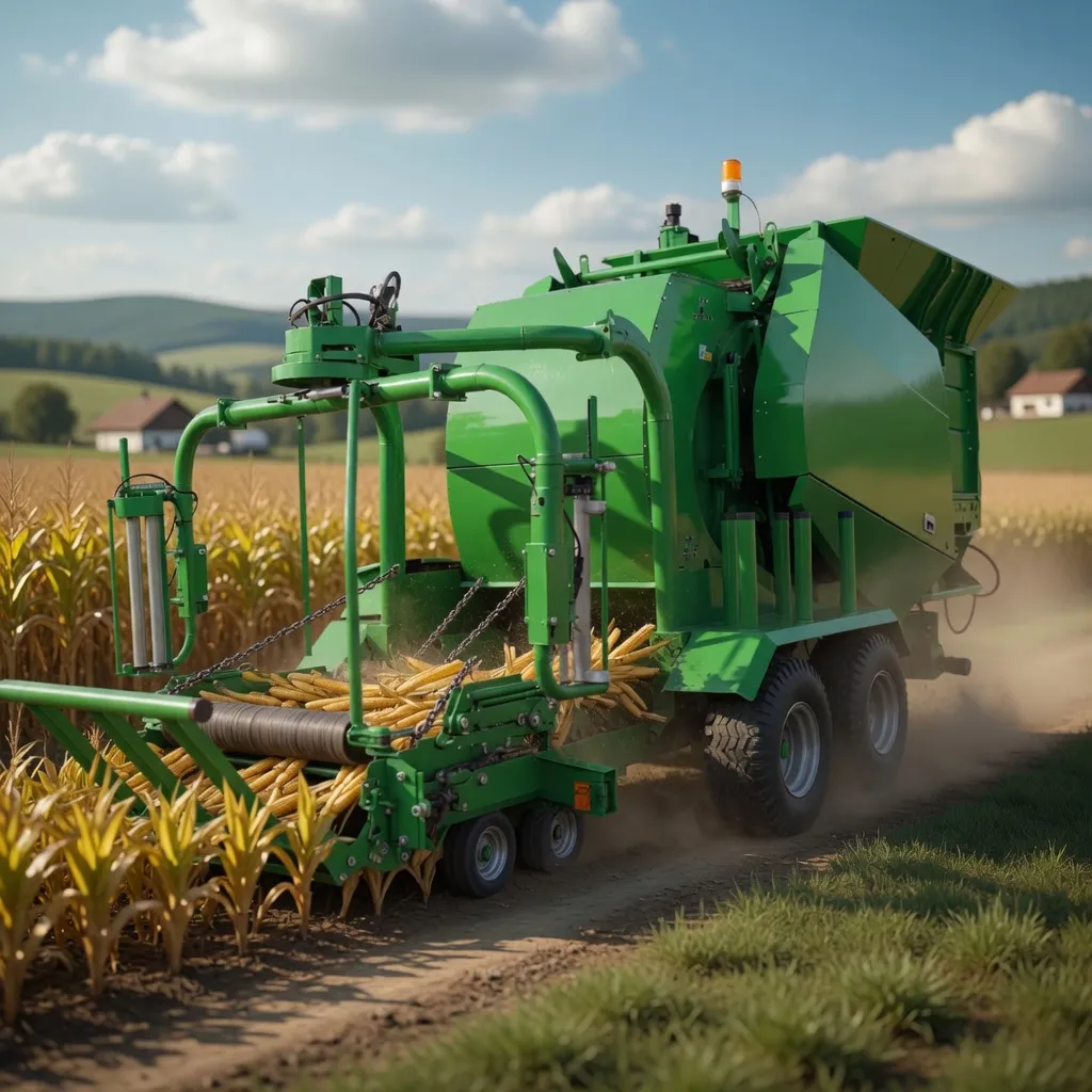
From baling to wrapping to grinding, every step in the forage chain is connected — maintaining quality at each stage ensures the feed value produced in the field reaches the feedbunk intact.
Power Consumption and Motor Load
The 9F-70 is rated at 11–15 kW. This rating describes the continuous power draw under full load with rated feed material at design throughput. Power consumption fluctuates significantly during normal operation: starting torque is high (3–5× running torque) as the rotor accelerates from rest, then drops to a moderate idle as the empty chamber spins, then rises as feed enters and the hammers engage material.
Three factors increase power draw beyond the rated figure: feeding material faster than the rated throughput (chamber overload), using a screen hole size finer than 4 mm (excessive recirculation), and feeding material above 20% moisture (wet material requires more energy to fracture and sticks to the screen, reducing open area). Operators should monitor motor temperature and current draw — a current reading consistently above the motor’s rated amperage signals that one of these three conditions exists and needs correction before motor thermal protection trips the circuit.
EverPower 9F-70: Built for Australian Feed Operations
The 9F-70 is available from EverPower Baling Machinery Australia at the Condell Park NSW warehouse. The machine is configured for Australian conditions: 415 V 3-phase electric motor or diesel alternative for off-grid properties, heavy-duty manganese steel hammers suited to the abrasive conditions of grinding dust-contaminated hay and sun-dried straw, and a rotor bearing specification adequate for continuous multi-shift operation. Replacement hammers, screens, bearings, and V-belts are stocked locally to ensure that a worn hammer set or failed bearing does not idle the machine for weeks waiting on an international parts order.
Recommended Product: 9F-70 Animal Feed Grass Grinder
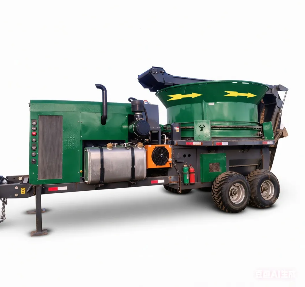
A 700 mm rotor hammer mill that processes dry hay, straw, and crop residues at 500–800 kg/hour into 4–15 mm particles. Reversible through-hardened hammers, CNC-punched interchangeable screens, and sealed rotor bearings provide reliable operation across Australian feed-production seasons. Electric (415 V 3-phase) and diesel options available. Local spare-parts support from Condell Park NSW.
Frequently Asked Questions
Want to See the 9F-70 Working on Your Feed Materials?
EverPower can advise on screen selection, power configuration, and throughput planning for hay, straw, stover, and mixed roughage operations.
EverPower Baling Machinery Australia Pty Ltd | 27 Harley Crescent, Condell Park NSW 2200
📞 +61 2 9708 3322 | ✉️ [email protected]