
Maintenance Is Where Grinder Performance Is Won or Lost
A hammer-mill forage grinder has relatively few moving parts compared to most farm machinery, but those parts operate under severe conditions: 2,800–3,200 RPM rotor speed, continuous high-impact fracture events, abrasive dust and grit in the grinding chamber, and temperature cycles from cold start to operating temperature multiple times per day. Under these conditions, the consumable components — hammers, screens, bearings, and belts — wear in ways that progressively degrade output quality before they fail outright. The challenge with forage grinder maintenance is that the performance decline caused by worn hammers or a partially blocked screen is gradual and easy to overlook until the ration quality is already affected. A proactive maintenance schedule, based on operating hours rather than visual inspection alone, keeps the 9F-70 producing within specification through the full feeding season and avoids the costly interruptions of unexpected breakdowns during peak grinding periods.
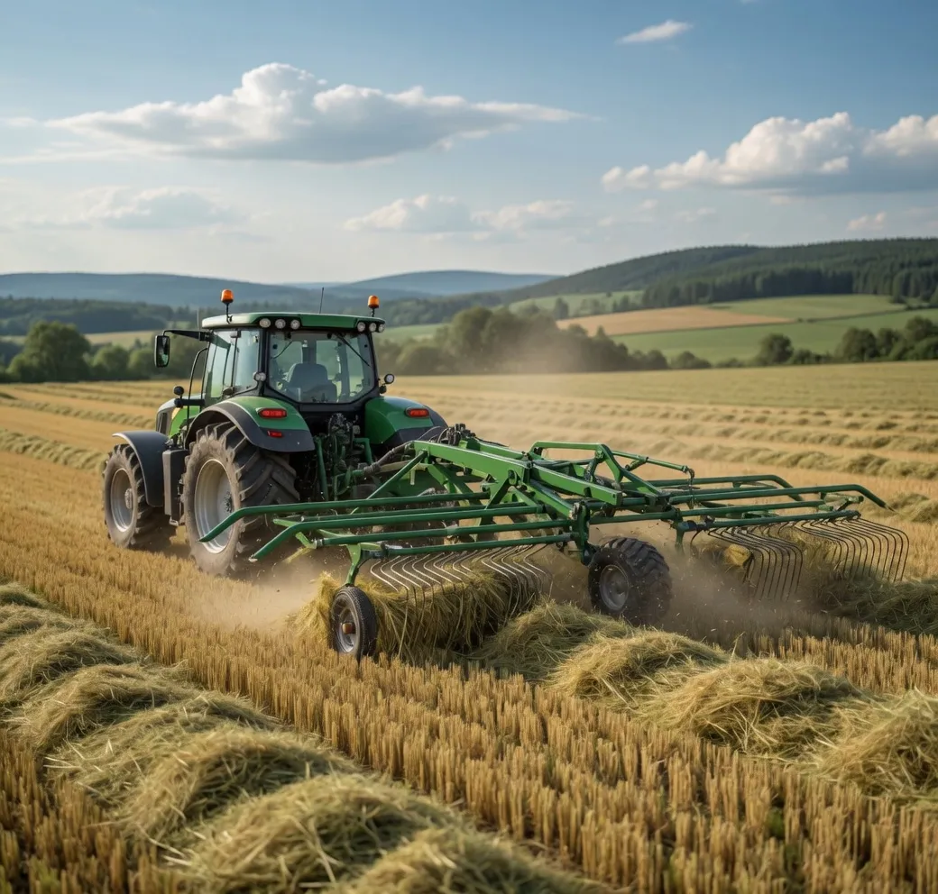
Like all farm machinery, a forage grinder operated on a proactive maintenance schedule delivers more reliable throughput and lower total cost than one maintained reactively after failures occur.
Hammer Maintenance: Flipping and Replacement Schedule
Hammers are the highest-wear component in the 9F-70. They are also the component whose condition most directly affects output particle size and throughput. Understanding the wear cycle — and acting on it at the correct point — is the single most impactful maintenance practice for a hammer-mill grinder.
New hammers have squared, well-defined striking edges. As the hammer strikes material, the leading edge rounds off progressively. This rounding reduces the kinetic energy transferred per strike — a rounded edge slides along the material surface partially rather than biting in and fracturing. The result is longer recirculation time, wider particle size distribution, higher motor load per tonne processed, and eventually visible throughput reduction.
The 9F-70 uses symmetric, reversible hammers — each hammer has two identical striking faces. At the flip interval, remove each hammer from its pivot pin, rotate it 180 degrees, and reinstall it. This presents the unworn face and restores fracture performance to near-new levels for another service interval. The flip procedure requires basic hand tools and takes approximately 30–45 minutes for the full hammer set with two people.
How to Replace Hammers on the 9F-70: Step by Step
Isolate the machine
Switch off the motor and disconnect the power supply (electric) or stop the engine and remove the ignition key (diesel). Wait for the rotor to come to a complete stop — confirm by listening for silence and checking that the rotor does not move when lightly touched through the feed inlet. Do not open the grinding chamber until full stop is confirmed.
Open the grinding chamber
Remove the bolts securing the chamber access panel (usually 4–6 bolts on the 9F-70). Swing the panel open and let any accumulated dust settle before leaning in. Wear a dust mask — grinding chamber dust contains fine silica and organic particles.
Remove and inspect each hammer
Slide the retaining cotter pin from each hammer pivot pin. Remove the pivot pin and slide the hammer off. Inspect the striking face: if one face is rounded and the other is still sharp (flip scenario), rotate 180 degrees and reinstall. If both faces are rounded, replace with a new hammer. Check the pivot pin for wear — grooves deeper than 0.5 mm indicate the pin should also be replaced.
Replace hammers in matched sets
Always replace or flip hammers as a complete set across the full rotor. Mixing worn and new hammers creates rotor mass imbalance — the rotor vibrates at operating speed, accelerating bearing wear and producing audible noise. Even if only one hammer is visibly worn, replace or flip all hammers on the same service visit.
Inspect the screen while the chamber is open
With the chamber open and the rotor stationary, inspect the screen for deformation, cracked holes, and material bridging. Poke blocked holes clear with a stiff wire brush. Replace the screen if any section is deformed or if hole edges are visibly worn smooth (worn hole edges allow oversized particles to flex through). Reinstall the access panel and torque bolts evenly.
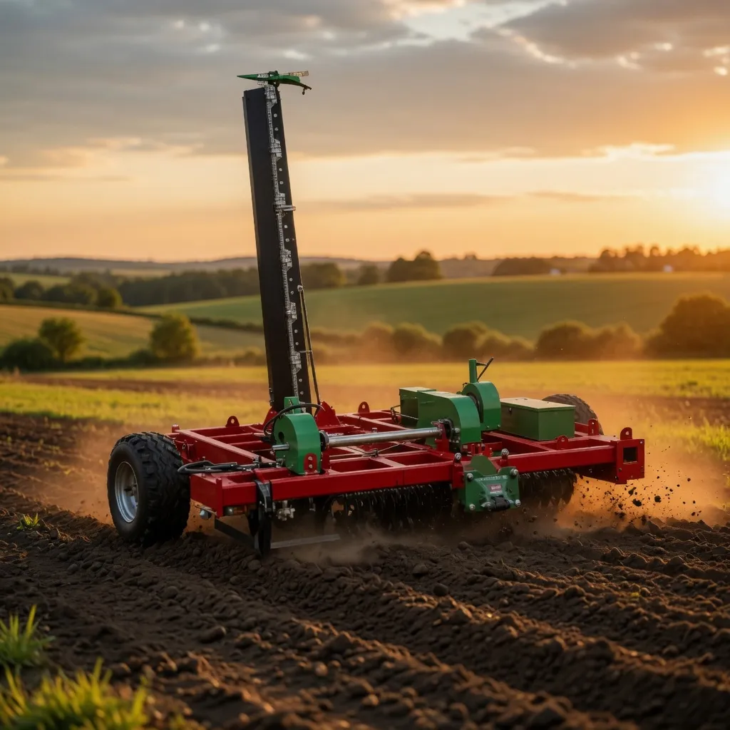
Maintenance done in the shed before the season starts avoids the breakdowns that occur during peak grinding periods — when replacement parts and repair time are hardest to find.
Screen Maintenance and Replacement
Screens are replaced less frequently than hammers but are equally critical to output quality. A worn or damaged screen produces oversized particles, increases motor load, and can pass foreign object fragments if holes crack or deform. Inspect the screen every time hammers are serviced, and replace it if any of the following are present: holes with worn, rounded edges rather than clean punched edges; deformed sections from stone or metal impact; bridged material that does not clear with a wire brush; or visible cracking around hole edges in the area of a previous impact.
Screen replacement frequency depends on material abrasiveness: hay screens typically last 600–800 hours before replacement is needed; straw and stover screens last 300–500 hours. Keep at least one spare screen for each size you use regularly. Waiting for a screen failure before ordering a replacement means the machine is idle during the shipping wait — a day of lost production is worth far more than the cost of a spare screen held in the parts bin.
Bearing and Belt Maintenance
Rotor bearings run at 2,800–3,200 RPM under continuous radial load from rotor mass and grinding forces. They are the component whose failure most severely damages the machine — a seized rotor bearing can damage the bearing housing, the rotor shaft, and the rotor assembly itself. Grease rotor bearings every 50 operating hours with a lithium-complex grease rated for high-speed applications. Do not over-grease — excess grease in a sealed bearing housing generates heat and accelerates rather than reduces wear. Two to three strokes of a standard grease gun per nipple per service interval is the correct quantity.
V-belts between the motor and rotor stretch in service and must be checked for tension monthly. A correctly tensioned belt deflects 10–15 mm under moderate thumb pressure midway between the pulleys. A loose belt slips under load, reducing rotor RPM, reducing tip speed, and producing a coarser, more variable particle size output. It also generates heat that shortens belt life. Replace belts when elongation exceeds the tension adjustment range — do not run on borderline-tension belts into peak season.
Recommended Product: 9F-70 Animal Feed Grass Grinder
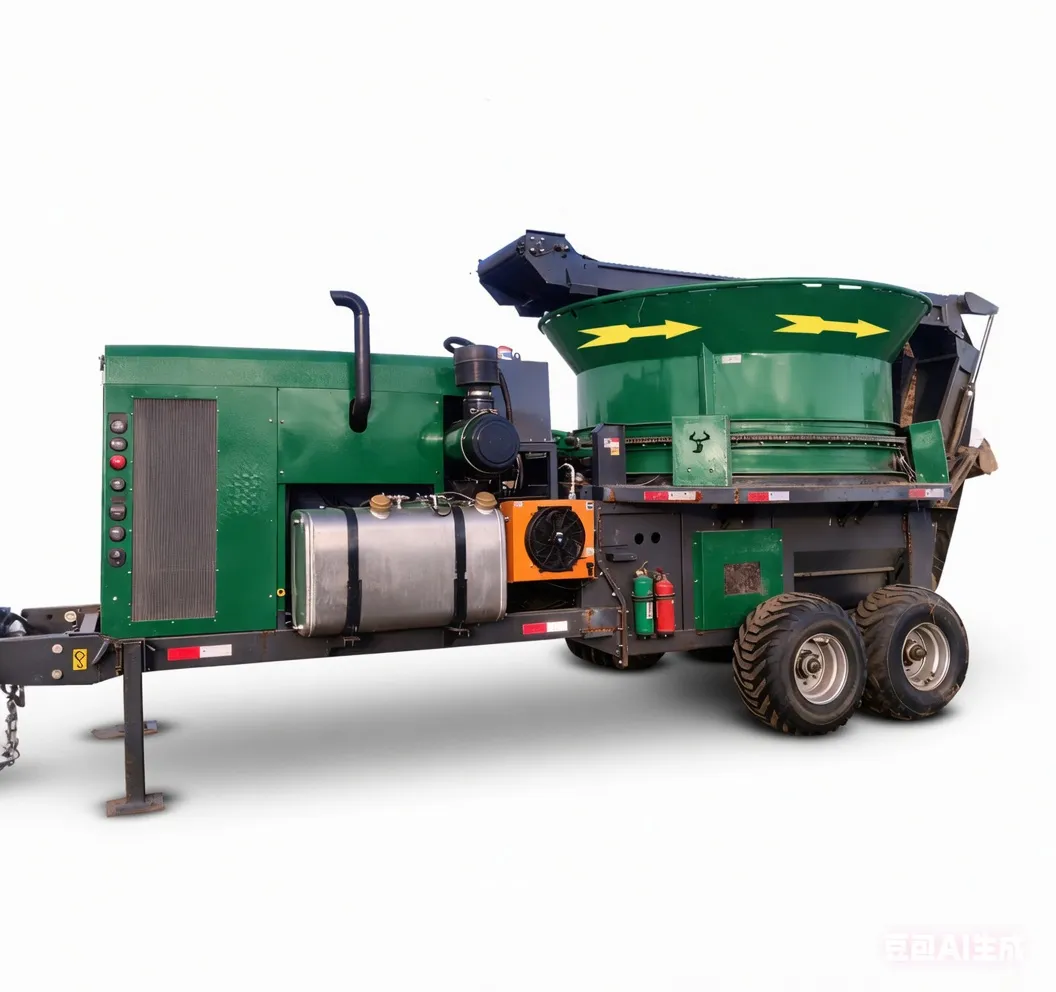
Reversible through-hardened manganese steel hammers, CNC-punched interchangeable screens, sealed heavy-duty rotor bearings. All wear parts — hammer sets, screens in four sizes, pivot pins, bearing kits, and V-belts — stocked at EverPower’s Condell Park NSW warehouse for same-day dispatch. Simple 30–45 minute hammer service with basic hand tools. Designed for Australian feed-production conditions.
Frequently Asked Questions
Keep Your 9F-70 Running at Full Performance.
EverPower stocks all wear parts for the 9F-70 and can advise on service schedules for your specific feed material and operating conditions.
Order Parts or Contact EverPower
EverPower Baling Machinery Australia Pty Ltd | 27 Harley Crescent, Condell Park NSW 2200
📞 +61 2 9708 3322 | ✉️ [email protected]